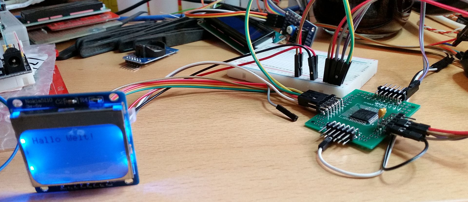
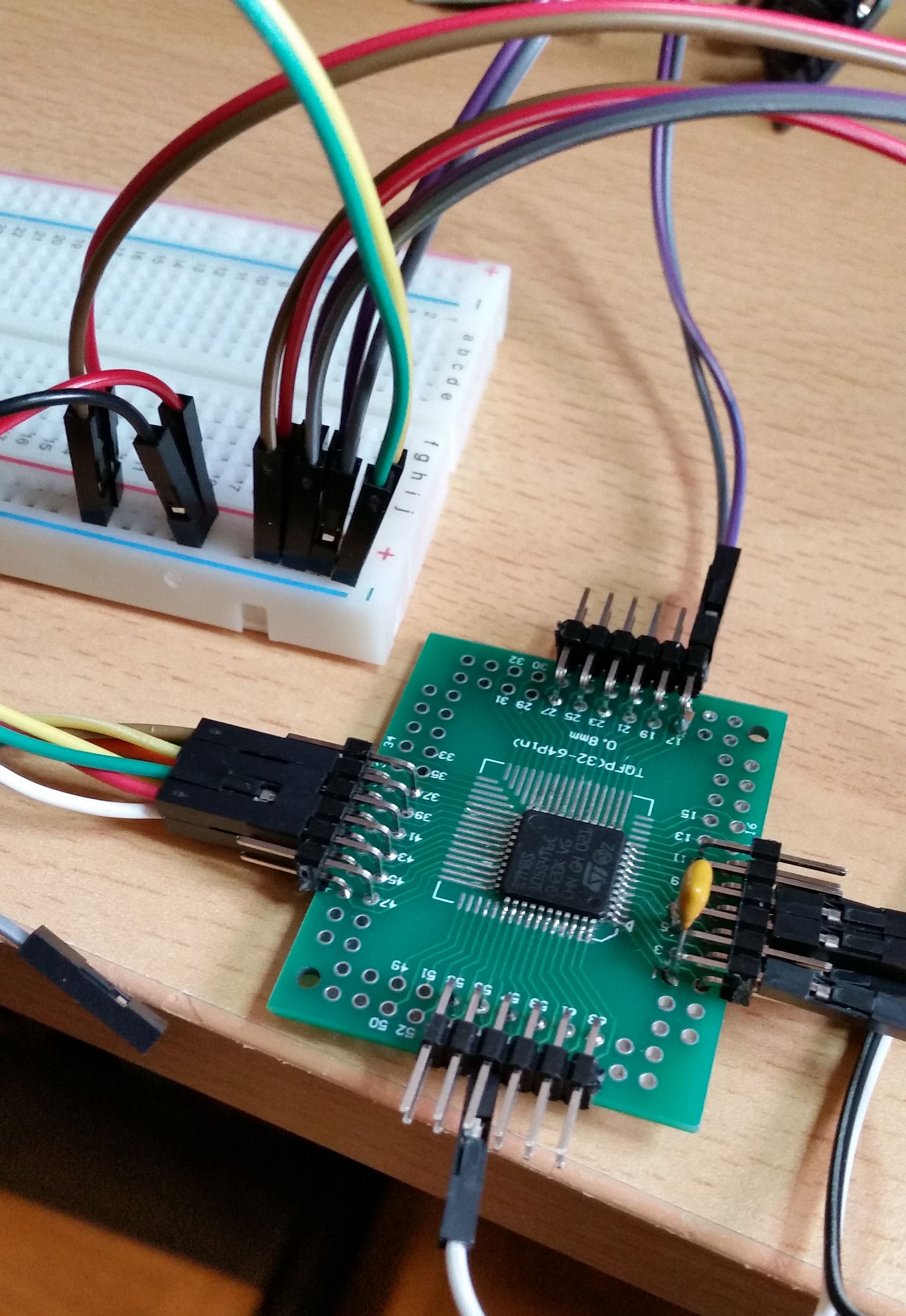
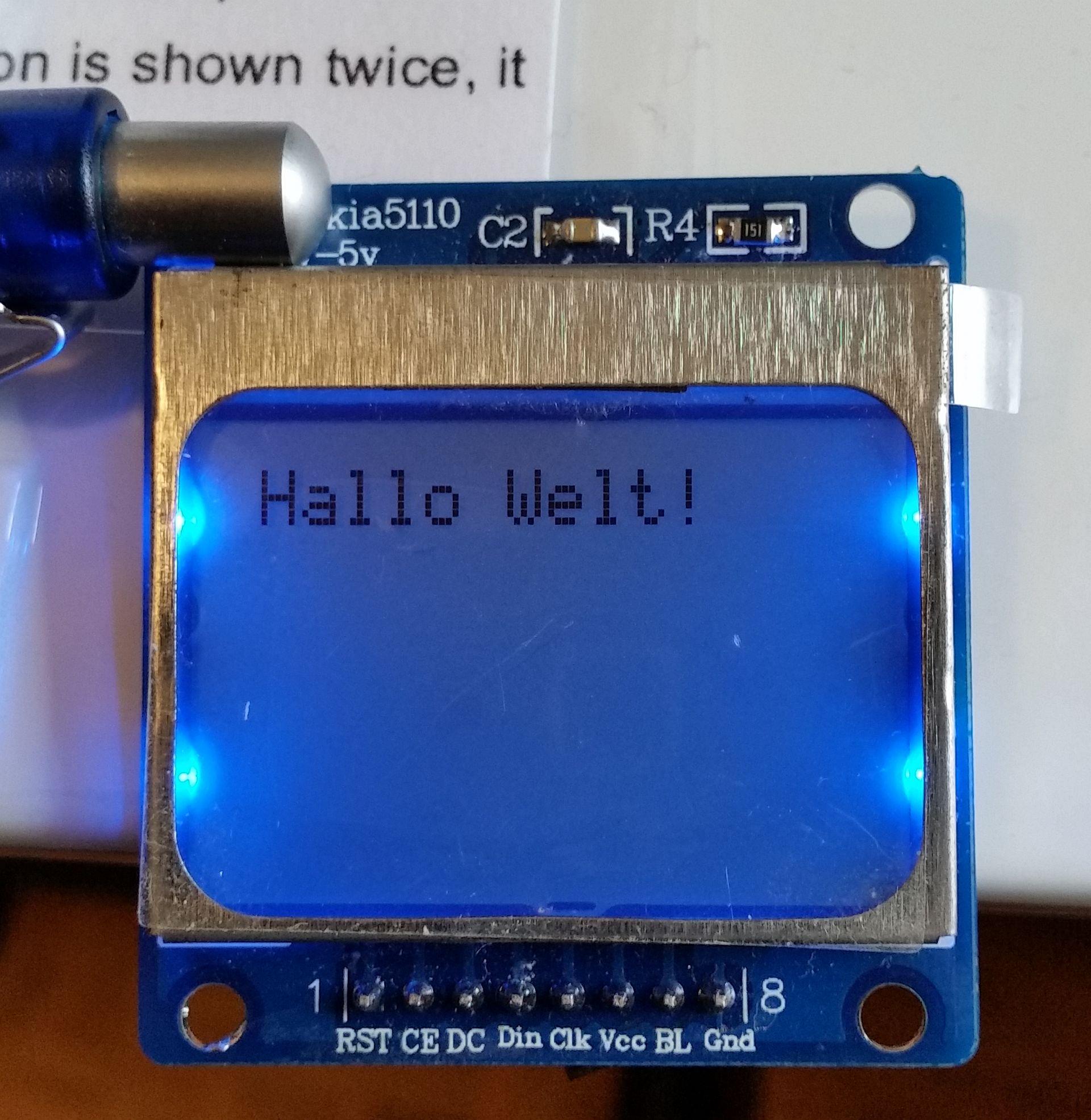
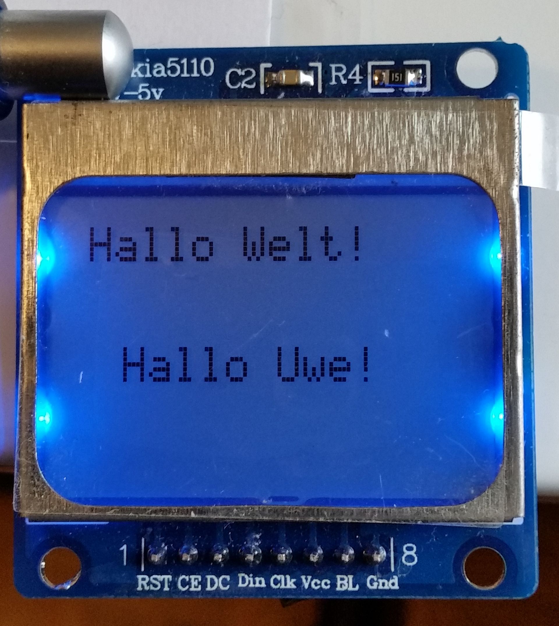
Die Software zum Schnelltest wurde von http://shelvin.de/lcd-display-nokia-5110-ansteuern/ übernommen und adaptiert:
// LCD Display vom Nokia 5110
// http://www.youtube.com/playlist?list=PLjzGSu1yGFjXWp5F4BPJg4ZJFbJcWeRzk
//
// Matthias Busse Version 1.3 vom 13.9.2014
// http://shelvin.de/lcd-display-nokia-5110-ansteuern/
//
// überarbeitet für STM8S105 von Uwe Grassow am 03.01.2016

#include <iostm8s105s4.h>
#include <intrinsics.h>
#include <stdint.h>
// #include "stm8_18b20.c"

static const uint8_t ASCII[][5] = {// ASCII Tabelle mit Fonts
 {0x00, 0x00, 0x00, 0x00, 0x00} // 20
,{0x00, 0x00, 0x5f, 0x00, 0x00} // 21 !
,{0x00, 0x07, 0x00, 0x07, 0x00} // 22 "
,{0x14, 0x7f, 0x14, 0x7f, 0x14} // 23 #
,{0x24, 0x2a, 0x7f, 0x2a, 0x12} // 24 $
,{0x23, 0x13, 0x08, 0x64, 0x62} // 25 %
,{0x36, 0x49, 0x55, 0x22, 0x50} // 26 &
,{0x00, 0x05, 0x03, 0x00, 0x00} // 27 '
,{0x00, 0x1c, 0x22, 0x41, 0x00} // 28 (
,{0x00, 0x41, 0x22, 0x1c, 0x00} // 29 )
,{0x14, 0x08, 0x3e, 0x08, 0x14} // 2a *
,{0x08, 0x08, 0x3e, 0x08, 0x08} // 2b +
,{0x00, 0x50, 0x30, 0x00, 0x00} // 2c ,
,{0x08, 0x08, 0x08, 0x08, 0x08} // 2d -
,{0x00, 0x60, 0x60, 0x00, 0x00} // 2e .
,{0x20, 0x10, 0x08, 0x04, 0x02} // 2f /
,{0x3e, 0x51, 0x49, 0x45, 0x3e} // 30 0
,{0x00, 0x42, 0x7f, 0x40, 0x00} // 31 1
,{0x42, 0x61, 0x51, 0x49, 0x46} // 32 2
,{0x21, 0x41, 0x45, 0x4b, 0x31} // 33 3
,{0x18, 0x14, 0x12, 0x7f, 0x10} // 34 4
,{0x27, 0x45, 0x45, 0x45, 0x39} // 35 5
,{0x3c, 0x4a, 0x49, 0x49, 0x30} // 36 6
,{0x01, 0x71, 0x09, 0x05, 0x03} // 37 7
,{0x36, 0x49, 0x49, 0x49, 0x36} // 38 8
,{0x06, 0x49, 0x49, 0x29, 0x1e} // 39 9
,{0x00, 0x36, 0x36, 0x00, 0x00} // 3a :
,{0x00, 0x56, 0x36, 0x00, 0x00} // 3b ;
,{0x08, 0x14, 0x22, 0x41, 0x00} // 3c <
,{0x14, 0x14, 0x14, 0x14, 0x14} // 3d =
,{0x00, 0x41, 0x22, 0x14, 0x08} // 3e >
,{0x02, 0x01, 0x51, 0x09, 0x06} // 3f ?
,{0x32, 0x49, 0x79, 0x41, 0x3e} // 40 @
,{0x7e, 0x11, 0x11, 0x11, 0x7e} // 41 A
,{0x7f, 0x49, 0x49, 0x49, 0x36} // 42 B
,{0x3e, 0x41, 0x41, 0x41, 0x22} // 43 C
,{0x7f, 0x41, 0x41, 0x22, 0x1c} // 44 D
,{0x7f, 0x49, 0x49, 0x49, 0x41} // 45 E
,{0x7f, 0x09, 0x09, 0x09, 0x01} // 46 F
,{0x3e, 0x41, 0x49, 0x49, 0x7a} // 47 G
,{0x7f, 0x08, 0x08, 0x08, 0x7f} // 48 H
,{0x00, 0x41, 0x7f, 0x41, 0x00} // 49 I
,{0x20, 0x40, 0x41, 0x3f, 0x01} // 4a J
,{0x7f, 0x08, 0x14, 0x22, 0x41} // 4b K
,{0x7f, 0x40, 0x40, 0x40, 0x40} // 4c L
,{0x7f, 0x02, 0x0c, 0x02, 0x7f} // 4d M
,{0x7f, 0x04, 0x08, 0x10, 0x7f} // 4e N
,{0x3e, 0x41, 0x41, 0x41, 0x3e} // 4f O
,{0x7f, 0x09, 0x09, 0x09, 0x06} // 50 P
,{0x3e, 0x41, 0x51, 0x21, 0x5e} // 51 Q
,{0x7f, 0x09, 0x19, 0x29, 0x46} // 52 R
,{0x46, 0x49, 0x49, 0x49, 0x31} // 53 S
,{0x01, 0x01, 0x7f, 0x01, 0x01} // 54 T
,{0x3f, 0x40, 0x40, 0x40, 0x3f} // 55 U
,{0x1f, 0x20, 0x40, 0x20, 0x1f} // 56 V
,{0x3f, 0x40, 0x38, 0x40, 0x3f} // 57 W
,{0x63, 0x14, 0x08, 0x14, 0x63} // 58 X
,{0x07, 0x08, 0x70, 0x08, 0x07} // 59 Y
,{0x61, 0x51, 0x49, 0x45, 0x43} // 5a Z
,{0x00, 0x7f, 0x41, 0x41, 0x00} // 5b [
,{0x02, 0x04, 0x08, 0x10, 0x20} // 5c ¥
,{0x00, 0x41, 0x41, 0x7f, 0x00} // 5d ]
,{0x04, 0x02, 0x01, 0x02, 0x04} // 5e ^
,{0x40, 0x40, 0x40, 0x40, 0x40} // 5f _
,{0x00, 0x01, 0x02, 0x04, 0x00} // 60 `
,{0x20, 0x54, 0x54, 0x54, 0x78} // 61 a
,{0x7f, 0x48, 0x44, 0x44, 0x38} // 62 b
,{0x38, 0x44, 0x44, 0x44, 0x20} // 63 c
,{0x38, 0x44, 0x44, 0x48, 0x7f} // 64 d
,{0x38, 0x54, 0x54, 0x54, 0x18} // 65 e
,{0x08, 0x7e, 0x09, 0x01, 0x02} // 66 f
,{0x0c, 0x52, 0x52, 0x52, 0x3e} // 67 g
,{0x7f, 0x08, 0x04, 0x04, 0x78} // 68 h
,{0x00, 0x44, 0x7d, 0x40, 0x00} // 69 i
,{0x20, 0x40, 0x44, 0x3d, 0x00} // 6a j
,{0x7f, 0x10, 0x28, 0x44, 0x00} // 6b k
,{0x00, 0x41, 0x7f, 0x40, 0x00} // 6c l
,{0x7c, 0x04, 0x18, 0x04, 0x78} // 6d m
,{0x7c, 0x08, 0x04, 0x04, 0x78} // 6e n
,{0x38, 0x44, 0x44, 0x44, 0x38} // 6f o
,{0x7c, 0x14, 0x14, 0x14, 0x08} // 70 p
,{0x08, 0x14, 0x14, 0x18, 0x7c} // 71 q
,{0x7c, 0x08, 0x04, 0x04, 0x08} // 72 r
,{0x48, 0x54, 0x54, 0x54, 0x20} // 73 s
,{0x04, 0x3f, 0x44, 0x40, 0x20} // 74 t
,{0x3c, 0x40, 0x40, 0x20, 0x7c} // 75 u
,{0x1c, 0x20, 0x40, 0x20, 0x1c} // 76 v
,{0x3c, 0x40, 0x30, 0x40, 0x3c} // 77 w
,{0x44, 0x28, 0x10, 0x28, 0x44} // 78 x
,{0x0c, 0x50, 0x50, 0x50, 0x3c} // 79 y
,{0x44, 0x64, 0x54, 0x4c, 0x44} // 7a z
,{0x00, 0x08, 0x36, 0x41, 0x00} // 7b {
,{0x00, 0x00, 0x7f, 0x00, 0x00} // 7c |
,{0x00, 0x41, 0x36, 0x08, 0x00} // 7d }
,{0x10, 0x08, 0x08, 0x10, 0x08} // 7e ?
,{0x78, 0x46, 0x41, 0x46, 0x78} // 7f ?
};

// Definition der benutzten Ports

#define RST PC_ODR_ODR1
#define CE PC_ODR_ODR2
#define DC PC_ODR_ODR3
#define DIN PC_ODR_ODR5
#define CLK PC_ODR_ODR6
#define BL PC_ODR_ODR7

#define DS18B20_Pin PG_IDR_IDR0;

#define LOW 0
#define HIGH 1
#define ON 1
#define OFF 0

void InitialisePort(){

  PC_DDR = 0xFF;                // alles output
  PC_CR1 = 0xFF;
  PC_CR2 = 0xFF;
  PC_ODR = 0x00;                // alle Ausgänge auf LOW
  PG_DDR_DDR0 = 0;
}

// Write byte to the module.

void shiftOut(uint8_t cmd) {

  uint8_t i;

  for (i = 8; i > 0; i--) {
    CLK = LOW;                                  // SPI_SCK = 0;
    if (cmd & 0x80) DIN = HIGH; else DIN = LOW; // SPI_MO = cmd & 0x80;
    cmd = cmd << 1;
    __no_operation();
    __no_operation();
    CLK = HIGH;                                 // SPI_SCK = 1;
  }
}

void LcdWriteCmd(uint8_t cmd){
  // Kommando an Display senden
  DC = LOW;             // DC pin is low for commands
  CE = LOW;
  shiftOut(cmd);        // transmit serial data
  CE = HIGH;
}

void LcdWriteData(uint8_t cmd){
  // Daten an Display senden
  DC = HIGH;            // DC pin is high for data
  CE = LOW;
  shiftOut(cmd);        // transmit serial data
  CE = HIGH;
}

void LcdClearScreen() {
  // Bildschirm leeren
  for(int i=0; i < 504; i++)
    LcdWriteData(0x00);
}

void LcdXY(int x, int y) {
  // an X / Y Position gehen
  LcdWriteCmd(0x80|x); // Spalte
  LcdWriteCmd(0x40|y); // Zeile
}

void LcdWriteCharacter(char character) {
  // ASCII Zeichen ausgeben aus der Tabelle oben
  for(int i=0; i < 5; i++) LcdWriteData(ASCII[character - 0x20][i]);
  LcdWriteData(0x00);
}


void LcdWriteString(char *characters) {
  // String ausgeben
  while(*characters) LcdWriteCharacter(*characters++);
}

void drawLine(void) {
    unsigned char j;
    for(j=0; j< 84; j++) { // top
    LcdXY (j,0);
    LcdWriteData (0x01); //
      }
    for(j=0; j< 84; j++) { //Bottom
    LcdXY (j,5);
    LcdWriteData (0x80); //
    }

    for(j=0; j< 6; j++) { // Right
    LcdXY (83,j);
    LcdWriteData (0xff); //
      }
    for(j=0; j< 6; j++) {// Left
    LcdXY (0,j);
    LcdWriteData (0xff); //
   }
  }


// klassische delay-Routine, Zeiten müssen noch berechnet werden, bisher Pi*Daumen geschätzt
volatile void delay(int millisek)
{
  int i=0; int j=0;
  for (j = 0; j < millisek; j++)
  {
    for (i=0; i<2000; i++) __no_operation();
  }
}

void LCDLight(uint8_t on_or_off)
{
    // Turn the backlight on or off by passing a bool value
    // The backlight takes 3.3V and can be either on or off

    if (on_or_off)
    {
        BL = ON;
    }
    else
    {
        BL = OFF;
    }
}


void main(){

  // setup
  InitialisePort();
  RST = LOW;
  delay(1);
  RST = HIGH;
  LcdWriteCmd(0x21); // LCD extended commands
  LcdWriteCmd(0xB3); //  Set LCD Vop (Contrast)
  // 0xB0 for 5V, 0xB1 for 3.3v, 0xBF if screen too dark
  LcdWriteCmd(0x04); // set temp coefficent
  LcdWriteCmd(0x14); // LCD bias mode 1:40
  LcdWriteCmd(0x20); // LCD basic commands
  LcdWriteCmd(0x0C); // LCD normal displaymode
  // 0x0D for inverse, 0x0C for normal


  LCDLight(ON);
  delay (100);
  LCDLight(OFF);
  delay (100);
  LCDLight(ON);
  delay (100);
  LCDLight(OFF);
  delay (100);
  LCDLight(ON);
  delay (100);
  LcdClearScreen();

  drawLine();
  LcdXY(25,2);
  LcdWriteString("Hallo");

// loop
  while(1)
  {

  LcdXY(30,3);
  LcdWriteString("Hallo Welt!");
  delay(500);

  LcdXY(30,3);
  LcdWriteString("Hallo Uwe! ");
  delay(500);
  }